
Mesh Solidify Roles: Shell Offset, Rims and Thickness
2026-11-06
Mesh Solidify Roles: Shell Offset, Rims and Thickness
Mesh Solidify Roles explain how a surface mesh can acquire depth through generated geometry. The shell, its position relative to the original surface and the faces joining boundary edges have different roles. Blender 4.5 documents them separately, which helps distinguish a thickness value from the location and topology of the geometry produced around it.
The input begins as a surface representation
Blender's official mesh structure reference identifies vertices, edges and faces as the basic mesh elements. Faces form the object's surface. A surface description therefore does not by itself specify two separated walls joined around their boundaries.
The official Solidify reference describes adding depth or thickness to a mesh surface. This changes geometry, rather than merely changing the way light is shaded on the original faces. The generated shell must consequently be followed as a geometric construction.
Thickness and offset answer different questions
Thickness describes the depth to be generated. Offset determines where the solidified output lies relative to the original mesh, with inside and outside interpreted using face normals. The documented centered case places the output around the original surface rather than entirely on one side.
These are separate relationships. Two conceptual shells can have the same stated depth but occupy different positions relative to the source surface. Conversely, knowing the shell is centered does not determine its depth. A drawing can retain the original surface as a reference line while showing the generated sides separately.

Rim faces join boundary edges
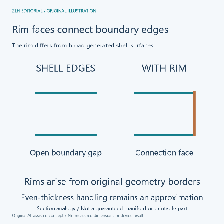
The Fill option addresses the gap between inner and outer edges. The reference explains that rims arise from borders of the original geometry. A rim is therefore a boundary connection, not another name for the broad surfaces parallel to the source.
The Only Rim descriptions make this distinction explicit. In Simple mode, it adds the perpendicular rim without the parallel extruded surfaces; in Complex mode, it leaves the generated perpendicular rim. Understanding the output requires identifying which class of faces remains, rather than assuming every solidify-related result contains a complete pair of shell surfaces.
The two algorithms have different topology capabilities
The manual describes Simple mode as an extrusion-based algorithm and notes that it does not support an edge with more than two adjacent faces. It also identifies inconsistent adjacent face-normal directions as a problem for solidifying the boundary in that mode.
Complex mode is designed for more difficult geometry and includes additional thickness and boundary handling. The extra logic has a computational cost. Its existence does not mean the words Simple and Complex are two interchangeable names for the same topology operation or that the slower choice is automatically required for every ordinary surface.
Local thickness and object scale belong together
The reference states that thickness is calculated using local vertex coordinates. With nonuniform object scale, the resulting thickness can differ on different sides in the transformed object. The coordinate context is therefore part of the geometric interpretation.
A local distance is not automatically the same as one uniform world-space wall thickness after different axis scale factors are involved. This follows the documented coordinate relationship; it is not a measurement of a manufactured part. The modifier's numeric input and a physical inspection result remain different objects.
Corner handling does not guarantee a constant wall everywhere
The manual discusses even-thickness handling and more advanced constraints, but its limitations section calls solidify thickness an approximation. Mesh topology, especially vertices with more than three adjacent faces, can affect the final wall thickness.
It explains that a universally precise construction could require adding or removing faces on the offset shell, which this modifier does not do in that general way. The availability of an Even or Constraints label should therefore be read with the stated limitation, rather than converted into an unconditional exact-thickness promise.
Vertex-group weights can also modify the generated thickness. The manual warns that a vertex with zero final thickness is still solidified and can create duplicate geometry. Zero separation consequently does not mean the generated geometric members have disappeared; coincident geometry and absent geometry are different results.
Generated shell and rim data can remain separately identified
The reference provides output vertex groups for shell and rim geometry. It also distinguishes material offsets for newly generated faces from the material assigned to rim faces. Those options preserve the fact that several classes of generated geometry can have different downstream uses.
Both complete Blender 4.5 references were read on November 6, 2026, including the topology and limitation sections. The original diagrams show shell placement and boundary connections without executing a modifier or specifying production wall dimensions. Related material appears in the 3D model geometry category and technical reference directory. Depth, placement, boundary connection and coordinate scale together describe the generated shell.