
Robot Curve Shapes: Control Points and Bezier Handles
2026-11-06
Robot Curve Shapes: Control Points and Bezier Handles
Robot Curve Shapes in a model can describe a cable outline, a drawn contour or an illustrative route through a scene. In Blender 4.4, a Bézier spline represents such a shape using control points and handles. Their roles explain why the visible curve can change while its main points stay in place, and why a smooth-looking line does not by itself describe a robot motion schedule.
A curve object can contain several splines
The Blender manual identifies splines as the fundamental components of curve objects. One curve object can contain multiple splines, much as one mesh object can contain disconnected mesh pieces. The object therefore supplies an organizational identity; it does not imply that every visible piece belongs to one continuous line.
The documented spline types include Poly, Bézier and NURBS. They use different representations. A Poly spline has no interpolation between its control points, while a Bézier spline uses handles to shape the connection. Calling a model element a curve is consequently less specific than identifying the spline type that defines its geometry.
Control points locate the ends of a segment
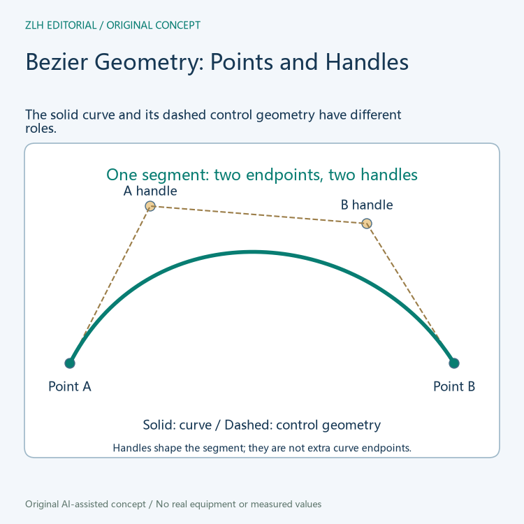
In the manual's Bézier description, a curve segment exists between two control points. Handles control the curvature of that segment. A control point and its handle consequently have different geometric roles even though both appear as editable markers in a diagram.
In the first original illustration, the solid segment meets its two endpoint markers. The two other markers belong to the control geometry and influence how the segment leaves one endpoint and approaches the other. The dashed polygon explains that relationship without treating all four markers as points through which the solid curve must pass. This makes a model annotation more informative than describing every marker as another corner of the curve.
Handle types constrain different aspects of shape
The Blender 4.4 Structure page lists four handle types. Automatic handles have their length and direction adjusted automatically for the smoothest curve. Vector handles point directly toward adjacent control points, allowing straight lines or sharp corners. These definitions explain two different ways that the neighboring control points can influence local shape.
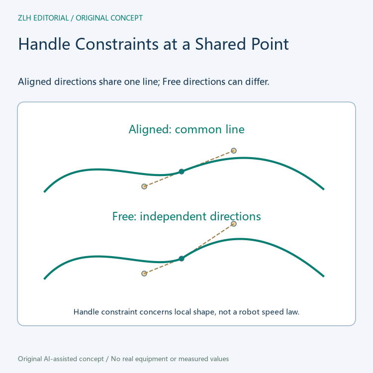
Aligned handles remain on a straight line. Free handles can move independently. At a shared point, an aligned pair therefore preserves a common line for the two sides, whereas independent handle directions allow a corner-like change. Collinearity concerns direction; it should not be read as a statement that the two handles must be the same distance from the point.
The manual also describes type changes when handles are moved: Automatic converts to Aligned, and Vector converts to Free. A description of the resulting curve should therefore preserve its actual handle type rather than assigning its original type permanently to the point. The definitions belong to Blender 4.4, the version used for both cited pages.
A shared tangent line does not fix every geometric property
The second illustration compares a shared point with collinear handle directions against a point with independent directions. Its purpose is to show the local constraint. The lines around the point still have surrounding geometry, and a common direction alone does not specify the whole segment shape or establish equal curvature on both sides.
This distinction is useful when reviewing a robot model appendix. A note can accurately say that handles are aligned while leaving the rest of the curve geometry to its actual model data. It need not expand that local condition into a claim about a perfectly circular arc, a constant radius or the mechanical bending behavior of a represented cable.
Moving points and changing tangents are different operations
The Control Points page gives a particularly useful distinction. Its Smooth operation reduces the distance between selected Bézier control points and their neighbors while keeping those neighbors anchored. The documentation says this does not affect the control-point tangents. The operation therefore concerns point positions, rather than being a general promise that every handle property is recalculated.
The same page separately describes Recalculate Handles as rotating selected handles to be tangential to the curve, with a Length option for equal handle lengths. These are distinct documented effects. A model review can identify whether the account concerns point locations, handle directions or handle lengths instead of compressing all three into the word smoothing.
Tilt describes another aspect of a three-dimensional curve
Blender's Tilt setting concerns how curve normals twist around control points and is relevant to three-dimensional curves. It is separate from the position-and-handle relationship that shapes the centerline. An arrow showing normal orientation should therefore retain that meaning rather than being mistaken for another Bézier handle.
For a scene reference, record the spline type, control-point geometry and relevant handle constraints alongside any separate tilt description. These establish what the modeled line represents. A physical robot trajectory would additionally need its own timing and motion context. Related explanations appear in the robot modeling collection and technical article directory. Both illustrations are original geometric examples rather than a screenshot or a processed robot model.
Sources: Blender 4.4, curve structure; Blender 4.4, control points.