
Vacuum Forming: Heated Sheets and Pressure Difference
2026-11-06
Vacuum Forming: Heated Sheets and Pressure Difference
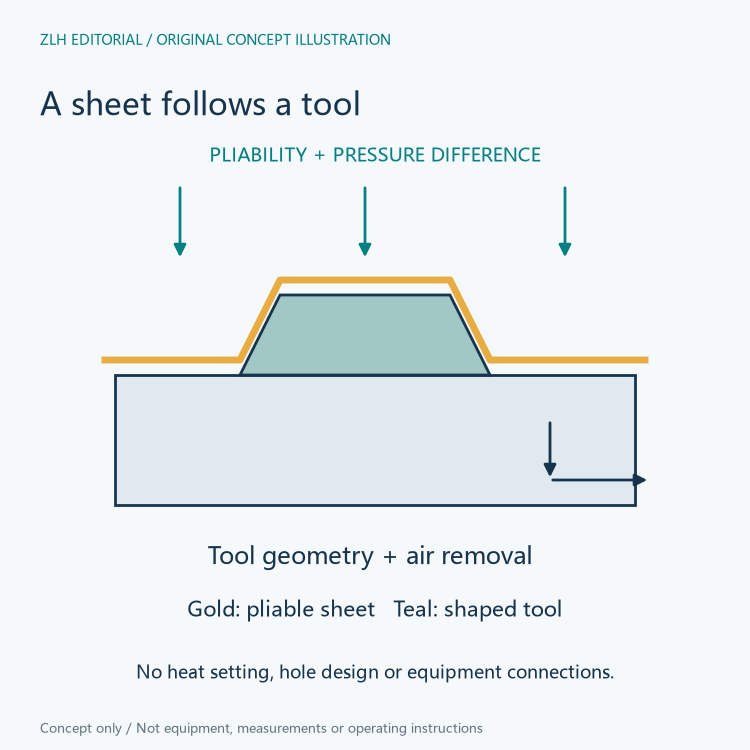
Vacuum Forming shapes an existing thermoplastic sheet rather than building the final object one deposited layer at a time. The sheet is heated until pliable, brought into a relationship with a shaped tool, and formed through a pressure difference as air is removed from the tool side. Cooling then allows the shaped plastic to retain the resulting form.
The starting material is a sheet
Formlabs' official introduction to vacuum forming describes a heated sheet pulled around a single mold using suction. Its broader thermoforming guide likewise identifies heating, shaping, cooling and trimming as parts of the process. Vacuum forming belongs within that broader thermoforming family.
This starting form matters to the explanation. The material already has a sheet geometry before it encounters the tool. Forming changes that geometry as the softened sheet conforms to the tool surface. Calling the process plastic molding without identifying the sheet would leave out a defining part of how the material reaches its shape.
The thermoforming guide names materials including ABS, polystyrene, polycarbonate and PETG, while relating the choice to the intended project and required part characteristics. These are examples of thermoplastic material families, rather than a claim that every sheet has the same forming behaviour. Material identity remains part of the process description alongside its starting sheet form.
Removing air creates the forming relationship
The thermoforming guide explains that the vacuum-forming machine removes air so the sheet is forced against the mold. The pressure difference across the pliable sheet is therefore part of the physical mechanism. The mold supplies the shape while the air-removal arrangement enables the sheet to approach that shape.
A tool is consequently more than a solid object placed under plastic. The two guides discuss ventilation as a tooling feature associated with the forming process. A technical drawing needs to distinguish the surface defining the part from the route by which air can leave, even when both belong to the same tooling assembly.
Positive and negative tools contact different faces
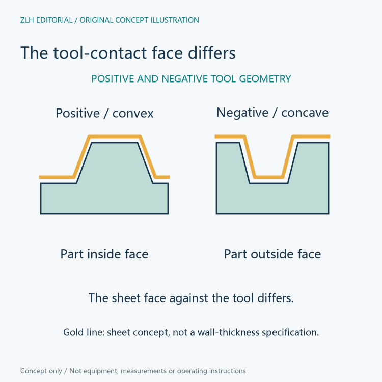
The vacuum-forming introduction distinguishes positive, convex tools from negative, concave tools. With a positive tool, the sheet contours over the protruding form. With a negative tool, it conforms within the recess. These geometries change which side of the formed part is directly associated with the tool surface.
The reference connects a positive mold with the inside dimensions of the plastic part and a negative mold with the outside dimensions. Thus, a finished shell's visible outside shape and the tool it was formed against need not have the same geometric description. Naming the contact face prevents a shortened tooling record from confusing the tool profile with the opposite face of the part.
Sheet thickness still belongs to the part description
Both guides identify uneven wall thickness as a limitation that can occur in thermoforming. The sheet's starting gauge and the geometry into which it is formed therefore remain relevant. Describing a tool-contact surface does not establish that every portion of the resulting wall has one uniform thickness.
The thermoforming guide separately discusses draw depth and the area that the sheet must cover. These relationships help explain why an overall footprint alone cannot describe a formed shell. A shallow tray and a deep contour may share a similar outline while demanding different changes in the sheet's geometry.
Cooling and trimming have different jobs
The source descriptions place cooling after forming. Once the plastic has taken the tool shape, it cools before release. Trimming then removes surrounding excess material or finishes the edge. Keeping those roles distinct makes it clear that forming the surface and defining the final perimeter are not necessarily the same event.
The general guide also distinguishes equipment that integrates trimming and cutting from arrangements where some work is carried out separately. A process summary can preserve the named stages without assuming that every machine performs them in the same station. The shared physical principle does not dictate one universal equipment layout.
A printed mold is tooling rather than the formed sheet
Formlabs discusses 3D printing as one route to making thermoforming tools, alongside machining, casting and other methods. In that arrangement the printed item supplies the mold geometry; the thermoplastic sheet supplies the formed part. These two objects can have different materials, manufacturing histories and service roles.
The guide relates tool choice to heat resistance, forming forces, surface finish and intended production context. A successful description therefore identifies both the tool and the sheet rather than transferring a printer-material property to the final shell. Related reading appears in the 3D manufacturing learning collection and technical article directory. The original illustrations separate material, pressure and contact geometry without giving forming settings.